If the chiller is the brain of a cooling system, the industrial pump is its heart, relentlessly pushing fluid to maintain a stable, efficient process. This vital component ensures that coolant flows through your system at precisely the right rate and pressure..
However, selecting a pump is not as simple as picking a horsepower rating. Incorrect sizing leads to a cascade of problems that can devastate your operation. Energy waste becomes a constant drain on your budget. The financial impact of pump sizing mistakes extends far beyond the initial purchase price.
An improperly sized pump can consume 20-50% more energy than necessary, while premature equipment failure can cost thousands in repairs and lost production time. The ripple effects touch every aspect of your cooling system’s performance.
This Industrial Pump Sizing Guide will demystify the pump sizing process for cooling systems. We’ll break down the essential steps, define key terms that matter, and explain why accurate sizing is crucial for your bottom line.
Understanding the Key Sizing Factors
Three critical parameters determine whether your pump will deliver reliable, efficient performance or become a source of ongoing problems.
Flow Rate (Q): The Volume of Fluid
Flow rate represents the amount of fluid that needs to move through your system per unit of time. This measurement directly correlates to your system’s cooling capacity and heat transfer requirements.
Common units include Gallons Per Minute (GPM) in imperial systems or Liters Per Minute (LPM) in metric applications. The required flow rate is often a fixed value based on your chiller or cooling tower manufacturer’s specifications.
For custom systems, engineers calculate this value based on the required heat load and the temperature differential across the system.
Determining the correct flow rate requires careful analysis of your cooling load. Insufficient flow leads to inadequate heat removal, while excessive flow wastes energy and can cause erosion in system components.
Total Dynamic Head (TDH): The Resistance to Flow
- Total Dynamic Head measures the total energy a pump must generate to overcome all resistance in your cooling system. Think of it as the “pressure” needed to move fluid through pipes, fittings, and equipment, expressed as a height of liquid in feet or meters.
- TDH consists of three key components that work together to determine your pump requirements
- It covers any additional pressure required at the discharge point. This might include pressure needed for spray nozzles, pressure vessels, or maintaining specific pressures at equipment inlet points.
The Third Critical Factor: Net Positive Suction Head (NPSH)
NPSH measures the pressure available at the pump’s suction port. This parameter prevents the fluid from vaporizing inside the pump, a destructive phenomenon known as cavitation.
- When NPSH falls below required levels, cavitation occurs. Vapor bubbles form in the low-pressure areas of the pump impeller, then violently collapse as they move to higher-pressure regions.
- This process creates a distinctive sound often described as “pumping gravel” and causes severe damage to the pump’s impeller and casing.
- Understanding NPSH requires considering fluid temperature, system elevation, and suction line friction losses.
- Higher temperatures reduce NPSH available, while longer suction lines with multiple fittings increase friction losses that further reduce available NPSH.
The Step-by-Step Pump Sizing Process
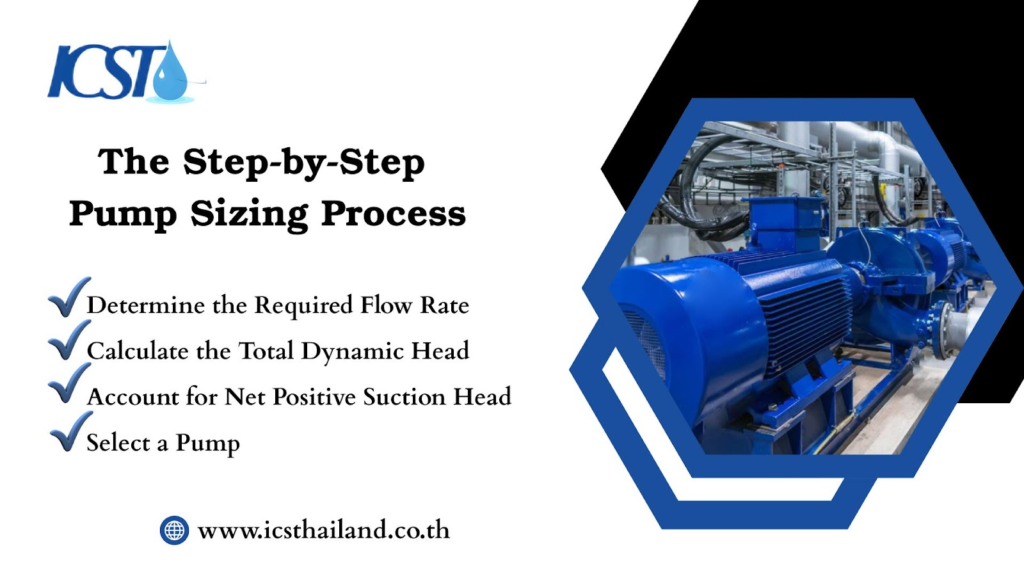
Proper pump sizing is essential for optimal performance and longevity. Our Industrial Pump Sizing Guide breaks down the systematic steps needed to determine your system requirements accurately.
Step 1: Determine the Required Flow Rate (Q)
Start by consulting manufacturer data sheets for your chiller, cooling tower, or other primary system components. These specifications provide the required GPM for optimal system performance.
For custom applications or retrofits, calculate flow rate based on the heat load equation:
Q = (Heat Load in BTU/hr) ÷ (500 × Temperature Differential).
This calculation assumes water as the cooling medium and provides a starting point for system design.
Step 2: Calculate the Total Dynamic Head (TDH)
This step requires the most detailed analysis and often determines the success or failure of your pump selection.
Measure the Static Head by finding the vertical distance from the pump centerline to the highest discharge point. Include any elevation changes in your piping layout, such as routing over obstacles or up to rooftop equipment.
Calculate the Friction Head through systematic analysis of every component in your system. Identify all pipe lengths and diameters throughout the flow path.
- Document every fitting, including elbows, tees, reducers, and valves. Account for equipment pressure drops across chillers, heat exchangers, filters, and flow meters.
- Professional engineers use specialized software or detailed friction loss charts to calculate resistance for each component.
- These calculations consider factors like Reynolds number, pipe roughness, and fluid properties to provide accurate pressure drop predictions.
Account for the Pressure Head by determining any required pressure at discharge points. This includes pressure needed for proper spray patterns in cooling towers, minimum inlet pressures for equipment, or pressure requirements for system control valves.
Step 3: Account for Net Positive Suction Head (NPSH)
The fundamental rule states that NPSH Available (NPSHA) must exceed NPSH Required (NPSHR) by a safety margin, typically 2-5 feet of head.
NPSHA depends on several system factors that change with operating conditions. Fluid temperature significantly affects vapor pressure. Higher temperatures reduce NPSHA.
System elevation influences atmospheric pressure, with higher elevations providing less pressure. Suction line configuration affects friction losses that subtract from available pressure.
Calculate NPSHA using the formula:
NPSHA = Atmospheric Pressure + Static Suction Head – Friction Losses – Vapor Pressure. Each component must be expressed in consistent units, typically feet of head.
Step 4: Select a Pump
- Use your calculated flow rate and TDH to plot a system curve on pump performance charts. The intersection of your system curve with the pump curve indicates the actual operating point.
- Target operation near the pump’s Best Efficiency Point (BEP) for optimal performance and longevity.
- Consider material compatibility with your cooling fluid, especially if using glycol mixtures or other specialty coolants.
- Evaluate motor options, including variable frequency drives for systems with varying loads.
The Cost of Getting It Wrong: Oversizing vs. Undersizing

Understanding the consequences of improper sizing reinforces the importance of careful calculation and professional expertise.
The Dangers of Oversizing
What seems like a conservative approach often creates more problems than it solves. How does excess capacity become a liability?
- Energy Waste: Oversized pumps operate inefficiently, consuming 20-50% more energy than properly sized units. The pump curve shifts away from the BEP, reducing overall efficiency and increasing operating costs.
- Premature Wear: Excessive flow rates accelerate erosion in pipes and fittings. Operation away from BEP increases vibration and stress on pump components, leading to bearing failures and mechanical seal problems.
- Control Issues: High flow rates make precise temperature and pressure control difficult. System response becomes sluggish, and control valves may operate in partially closed positions, creating additional pressure drops and energy waste.
The Dangers of Undersizing
Insufficient pump capacity creates immediate operational problems that worsen over time. What happens when your pump cannot meet system demands?
- Inadequate Cooling: The pump cannot deliver the required flow rate or pressure, leading to poor heat transfer and equipment overheating. Process temperatures rise beyond acceptable limits, threatening product quality and equipment reliability.
- Component Strain: Operating beyond design limits forces the pump to work harder than intended. This leads to frequent breakdowns, increased maintenance costs, and dramatically shortened equipment lifespan.
- System Instability: Insufficient flow creates temperature variations throughout the system. Hot spots develop in critical areas, while other zones may overcool, creating thermal stress and reducing overall system efficiency.
Conclusion
Proper pump sizing represents a crucial engineering task that directly impacts your cooling system’s efficiency, reliability, and operating cost. The calculations involve complex interactions between fluid dynamics, thermodynamics, and mechanical engineering principles.
While this guide provides essential knowledge for understanding the process, precise calculation of TDH, accurate NPSH analysis, and optimal pump selection require experienced professionals. The margin for error is small, and the consequences of mistakes are significant.
Ready to ensure your industrial cooling system runs perfectly? Get a professional pump sizing assessment! Chat with our experienced engineers who truly get the ins and outs of industrial pumps. They will make sure you get an efficient and reliable setup every time. Visit the ICST website for more information.
Frequently Asked Question
What are the three key factors for sizing an industrial pump?
The three key factors are Flow Rate (Q), Total Dynamic Head (TDH), and Net Positive Suction Head (NPSH).
What is Total Dynamic Head (TDH)?
TDH is the total energy a pump needs to overcome all resistance in a cooling system. It includes static head, friction head, and pressure head.
What is the difference between a static head and a friction head?
Static head is the vertical distance the fluid needs to be lifted, while friction head is the energy loss due to friction within pipes, valves, and fittings.
Why is Net Positive Suction Head (NPSH) important?
NPSH is important because it measures the pressure at the pump’s suction port, which must be high enough to prevent cavitation, a destructive process that can severely damage the pump.
What is the main danger of oversizing a pump?
The main danger is significant energy waste, with oversized pumps consuming 20-50% more energy than necessary. It can also cause premature wear and control issues.
How do I calculate the required flow rate (Q) for my system?
You can determine the flow rate by consulting manufacturer data sheets for your chiller or cooling tower, or by using the heat load equation: Q=(HeatLoad)/(500×Temperature Differential).