While the energy efficiency and low-maintenance perks of magnetic bearing fan technology are well-known, they’re only part of the story. For engineers, consultants, and plant designers, a deeper dive into the mechanics is essential for correct system specification.
This article moves beyond general benefits to explore the engineering principles that make magnetic bearing fans a superior choice for critical applications. We examine the physics of rotor levitation, the architecture of the control systems, and the specific integration requirements for modern industrial environments.
By understanding the core components and operational logic of this contactless bearing system, engineers can better evaluate its suitability for complex cooling infrastructure.
Evolution of Bearing Systems in Industrial Fan Design
Industrial fan design has evolved significantly over the last century, driven by a need for higher speeds, reduced friction, and lower maintenance. The progression from simple mechanical support to sophisticated active control highlights the industry’s shift toward precision engineering.
Tracing this evolution reveals how engineers have systematically eliminated points of failure:
- Sleeve Bearings: The earliest standard, relying on oil film and direct contact, is often limited by high friction and heat generation.
- Ball & Roller Bearings: Reduced friction significantly but introduced metal-to-metal contact, requiring regular lubrication and eventual replacement due to fatigue.
- Fluid Film Bearings: Utilized a pressurized oil wedge to support the shaft, effective for high loads but requiring complex oil systems.
- Air Foil Bearings: Eliminated oil by using air pressure for lift, though they still require contact during start/stop phases.
- Magnetic Bearing Systems: The current pinnacle of design, utilizing electromagnetic forces to suspend the rotor, eliminating all physical contact and lubrication.
Bearing Technologies in Industrial Fans
| Bearing Type | Physical Contact | Lubrication Required | Wear Rate | Control Capability | Typical Application |
| Sleeve | High | Yes (Oil/Grease) | High | None | Low-speed general HVAC |
| Ball / Roller | Moderate | Yes (Grease) | Moderate | None | Standard industrial fans |
| Fluid Film | Low (at speed) | Yes (Oil system) | Low | Passive | Heavy-duty turbines |
| Air Foil | Start/Stop only | No | Low | Passive | Microturbines, blowers |
| Magnetic | None | No | Negligible | Active | High-speed chillers, critical cooling |
The Working Principle of Magnetic Bearing Fan Technology
The fundamental operation of magnetic bearing fan technology relies on the precise application of electromagnetic forces to counteract gravity and dynamic loads. Unlike mechanical bearings that react passively to forces, magnetic bearings actively manage the rotor position.
The system typically employs heteropolar electromagnets arranged radially around the rotor shaft. Position sensors detect the exact location of the shaft thousands of times per second. If the shaft deviates from the center, the controller adjusts the current supplied to the electromagnets.
This creates a magnetic field that pulls the shaft back to the geometric center. This continuous adjustment allows the rotor to spin around its inertial axis rather than its geometric axis, significantly reducing vibration.
Core Components of a Magnetic Bearing Fan System
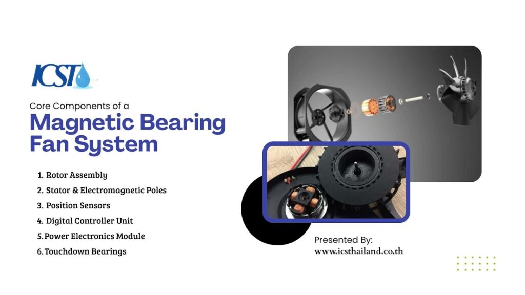
A magnetic bearing system is not a single component but an integrated mechatronic assembly. Each part plays a critical role in maintaining the contactless bearing system and ensuring operational stability.
Rotor Assembly
The rotor is the rotating part of the machine, equipped with ferromagnetic laminations. These laminations interact with the magnetic field generated by the stator. Because there is no physical contact, the rotor requires high tensile strength materials to withstand centrifugal forces at high rotational speeds.
Stator & Electromagnetic Poles
The stator houses the copper windings that generate the magnetic field. These are typically arranged in quadrants to provide control along the X and Y axes. The current flowing through these coils determines the strength of the magnetic attraction.
Position Sensors
Inductive or eddy-current sensors are located adjacent to the bearings. They measure radial and axial displacement with micron-level accuracy. The data from these sensors provides the feedback necessary for the control loop to function.
Digital Controller Unit
The controller is the brain of the system, usually consisting of a Digital Signal Processor (DSP) or a Field Programmable Gate Array (FPGA). It processes the sensor data and executes complex algorithms to determine the necessary current adjustments for the electromagnets.
Power Electronics Module
This amplifier converts the low-voltage control signals from the digital controller into the high-current power required by the electromagnetic coils. It must respond rapidly to ensure the magnetic field changes instantly to correct the shaft position.
Backup / Touchdown Bearings
Safety is paramount in magnetic bearing fan technology. Backup bearings, typically ceramic ball bearings, sit slightly away from the shaft during normal operation. They only engage if the magnetic system fails or powers down, allowing the rotor to coast to a stop without damaging the magnetic coils.
Active Control System Architecture
The distinction of a magnetic levitation fan lies in its active control system. This is a closed-loop feedback mechanism that maintains stability under varying conditions.
The control architecture typically follows a PID (Proportional-Integral-Derivative) logic:
- Proportional: Corrects the immediate error in position.
- Integral: Corrects steady-state errors over time.
- Derivative: Predicts future errors based on the rate of change.
This system monitors shaft displacement in real-time. When a disturbance occurs—such as a sudden change in airflow demand—the controller detects the movement within microseconds. It then commands the power electronics to alter the magnetic field intensity, stiffening the “magnetic spring” to resist the load.
This capability allows the fan to integrate seamlessly with Variable Frequency Drives (VFDs) for precise speed control.
Load Management & Dynamic Stability
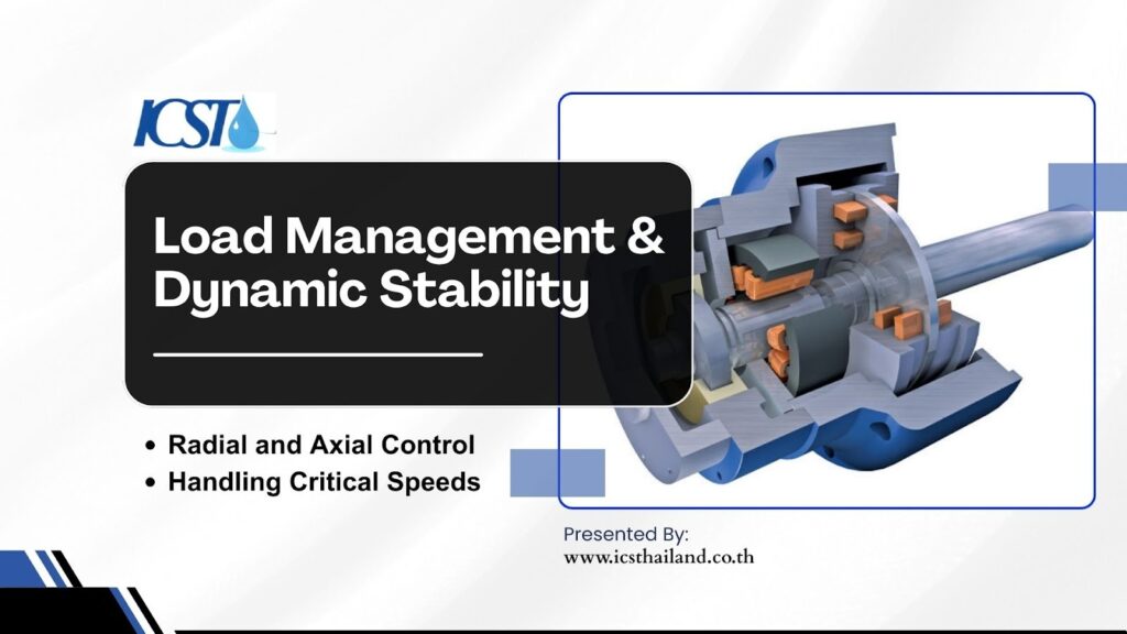
Engineers must understand how an advanced fan control system manages mechanical loads. Unlike rigid mechanical bearings, magnetic bearings offer variable stiffness and damping.
Radial and Axial Control
The system manages loads in two primary directions. Radial bearings support the weight of the rotor and resist imbalance forces. Axial bearings (or thrust bearings) counteract the thrust generated by the fan blades. The controller balances these forces simultaneously, ensuring the rotor remains levitated even during surge conditions.
Handling Critical Speeds
Every rotating shaft has natural resonant frequencies or “critical speeds.” Conventional bearings must pass through these quickly to avoid damage. Magnetic bearings, however, can alter their damping characteristics electronically.
The controller can actively suppress vibration as the shaft passes through critical speeds, allowing for a smoother ramp-up to operating velocity.
Power Requirements & Electrical Considerations
Because the levitation is electrical rather than mechanical, the power quality supplied to the unit is a critical design consideration.
Ensuring continuous operation requires specific electrical infrastructure planning:
- Uninterruptible Power Supply (UPS): A dedicated UPS is often integrated into the drive or required externally. This ensures that if utility power is lost, the magnetic bearings remain energized long enough for the rotor to coast down onto the backup bearings safely.
- Harmonic Distortion: High-speed drives can generate harmonic noise. Engineers must verify that the magnetic bearing fan technology includes appropriate line reactors or filters to prevent these harmonics from affecting the facility’s power grid.
- Power Redundancy: For mission-critical applications like data centers, dual power feeds to the fan controller provide an additional layer of reliability.
Installation & Commissioning Guidelines
While oil-free industrial fan systems reduce long-term maintenance, they require precision during the initial installation.
Successful commissioning depends on strict adherence to these protocols:
- Structural Rigidity: The mounting base must be rigid. If the foundation vibrates at the same frequency as the control loop, it can cause instability.
- Levitation Calibration: Before the fan runs, technicians perform a static levitation test. This calibrates the center point of the shaft relative to the backup bearings.
- Vibration Baseline: A baseline vibration signature does not just confirm balance; it validates that the active control system is correctly tuning out harmonic disturbances.
Magnetic Bearing vs Air Foil vs Conventional Bearings
Comparing bearing types side-by-side clarifies why magnetic bearing fan technology is specified for high-performance applications.
Technical Comparison
| Feature | Magnetic Bearing | Air Foil Bearing | Ball / Roller Bearing |
| Contact During Operation | None | None (Above lift-off speed) | Constant |
| Lubrication | None | None | Grease / Oil |
| Active Control | Yes (Real-time adjustment) | No (Passive aerodynamic) | No |
| Response to Load Changes | High (Adjustable stiffness) | Low (Risk of contact) | Moderate (Rigid) |
| Complexity Level | High (Requires electronics) | Moderate (Precision geometric) | Low (Mechanical) |
| Ideal Operating Environment | Variable speed, high load | Constant high speed | Constant speed, moderate load |
System Integration in Modern Cooling Infrastructure
Integrating magnetic bearing fan technology into a broader cooling plant involves more than just piping and power connections.
Modern integration strategies focus on data connectivity and automation:
- Direct-Drive Coupling: These fans usually eliminate gearboxes, coupling directly to high-speed permanent magnet motors. This reduces the footprint and mechanical loss.
- Smart Monitoring: The position sensors used for levitation provide diagnostic data. The system can report imbalance, vibration trends, and bearing loads to the Building Management System (BMS) via Modbus or BACnet.
- Data-Driven Optimization: By analyzing the power consumption and speed data, the central plant controller can optimize the entire cooling array, shifting loads to fans operating in their most efficient range.
When Magnetic Bearing Fan Technology May Not Be Ideal
Despite its advantages, there are scenarios where magnetic bearings may not be the optimal engineering choice.
Engineers should reconsider this technology in the following situations:
- Unstable Power Grids: In regions with frequent, dirty power and insufficient UPS infrastructure, the risk of dropping onto backup bearings increases, leading to premature wear.
- Low Duty Cycles: The return on investment relies on efficiency gains during operation. For standby fans that run rarely, the high initial capital cost may not be justifiable.
- Extreme Environments: While robust, the sophisticated electronics require protection from extreme heat, moisture, or conductive dust that might be tolerable for a simple ruggedized induction motor.
Conclusion
The shift toward magnetic bearing fan technology represents a fundamental change in how we approach rotating machinery. By replacing mechanical constraints with electronic precision, engineers gain unprecedented control over system dynamics.
We are moving away from passive components that wear down and toward active systems that adapt. The ability of magnetic bearing fans to self-balance, monitor their own health, and operate without friction aligns perfectly with the demands of modern, automated infrastructure.
For the contactless bearing system, the future is not just about eliminating oil; it is about integrating intelligent, reliable, and precise control into the heart of industrial cooling. Visit the ICST website for quality parts like fans, motors, and gearboxes.
Frequently Asked Questions
What is magnetic bearing fan technology?
Magnetic bearing fan technology uses electromagnetic forces to levitate and stabilize the rotor without physical contact. This eliminates friction, lubrication, and mechanical wear during operation.
How do magnetic bearings work in industrial fans?
They use position sensors and an active control system to monitor shaft location in real time. Electromagnets automatically adjust current to keep the rotor centered and stable.
What are the main components of a magnetic bearing fan system?
Key components include the rotor assembly, stator with electromagnetic coils, position sensors, digital controller (DSP/FPGA), power electronics module, and backup bearings.
What happens if power fails in a magnetic bearing fan?
Most systems include a UPS to maintain levitation during shutdown. If power is lost completely, backup (touchdown) bearings safely support the rotor.