Cooling tower seismic design requirements focus on ensuring structural resilience during seismic events. Key elements include robust anchor bolt systems, cross bracing, and compliance with ASCE 7 and IBC codes. These requirements address seismic loads, dynamic fluid sloshing, and lateral forces to prevent structural failure.
Proper design incorporates flexible piping connections, ductile anchor bolts, and load distribution systems to maintain operational safety. Meeting these standards protects critical infrastructure, ensures code compliance, and minimizes risks during earthquakes, safeguarding both human life and facility operations.
The Seismic Vulnerability of Cooling Towers: The Elevated Mass Hazard
Cooling towers present unique challenges compared to standard buildings. They hold massive amounts of operational water weight high above the ground. This elevated mass inside hot-water basins, heavy fill packs, and cold-water sumps creates a dangerous fluid pendulum effect.
Dynamic fluid sloshing occurs when lateral ground motion violently shifts the water. The water crashes against the basin walls, immediately changing the center of mass. This dynamic behavior magnifies lateral forces and seismic loads against the supporting frame. Static methods and static analysis often fail to account for this fluid movement.
Engineers must navigate the International Building Code (IBC) and ASCE 7. Classifying the tower as a non-structural mechanical component (Chapter 13) or a standalone non-building structure (Chapter 15) dictates the minimum design loads. Identifying the correct risk category and site class ensures code compliance and structural integrity.
Structural Sizing & Load Requirements Matrix
Every structural component along the lateral load path requires rigorous engineering. We use specific load combinations, including the ultimate seismic force equation ($1.2D + 1.0E + L$), to guarantee a robust design.
| Structural Component | Seismic Engineering Mandate | Critical Failure Mode Prevented |
| Foundation & Plinths | High-performance concrete (≥ 4,000 PSI) with dedicated pier blocks | Foundation cracking and concrete shear cone breakouts |
| Anchor Bolt System | Cracked-concrete certified expansion or heavy adhesive anchors | Anchor pull-out, thread stripping, and edge blowout |
| Structural Frame | Redundant diagonal cross-bracing or heavy, rigid moment frames | Structural racking and catastrophic framing collapse |
| Header Piping Interfaces | Braided multi-directional flexible connections | Main manifold shear and fiberglass basin flange fractures |
- Foundation and Plinths: We use high-performance concrete with dedicated pier blocks and spread footings. This prevents foundation cracking and concrete shear cone breakouts. Ignoring soil structure interaction here leads to severe foundational failure.
- Anchor Bolt System: We deploy cracked-concrete certified expansion or heavy adhesive anchors. This robust design stops anchor pull-out, thread stripping, and edge blowout.
- Structural Frame: Redundant diagonal cross bracing or rigid moment frames distribute lateral loads effectively. This prevents structural racking and catastrophic framing collapse.
- Header Piping Interfaces: We implement braided multi-directional flexible connections. These protect the main manifolds from shear damage and fiberglass basin fractures.
Decoding the Seismic Design Force ($F_p$) Formula
ASCE 7 Chapter 13 specifies the precise mathematical guidelines used to calculate base shear forces. These metrics determine the horizontal forces required to secure your mechanical systems.
The core equation is:
F_p = \frac{0.4 \cdot a_p \cdot S_{DS} \cdot W_p}{\left(\frac{R_p}{I_p}\right)} \left(1 + 2\frac{z}{h}\right)
The Component Importance Factor (I_p)
The importance factor scales your structural requirements based on facility use.
- I_p = 1.0 (Standard Commercial): We design the equipment purely to protect human life. The tower must not collapse.
- I_p = 1.5 (Designated Seismic System): Data centers and hospitals mandate this rating. The critical infrastructure must remain fully operational after an earthquake.
Amplification (a_p) and Response (R_p)
These variables measure structural response and flexibility. They calculate how the acceleration forces transfer from the ground into the structure. Flexible units behave differently from rigid ones, requiring specific adjustments to match their natural frequencies.
Advanced Anchor Bolt Design & Ductility (ACI 318 Appendix D)
Anchor bolt design requires exact mathematical precision. Common mistakes here lead to immediate structural failure during high seismic activity.
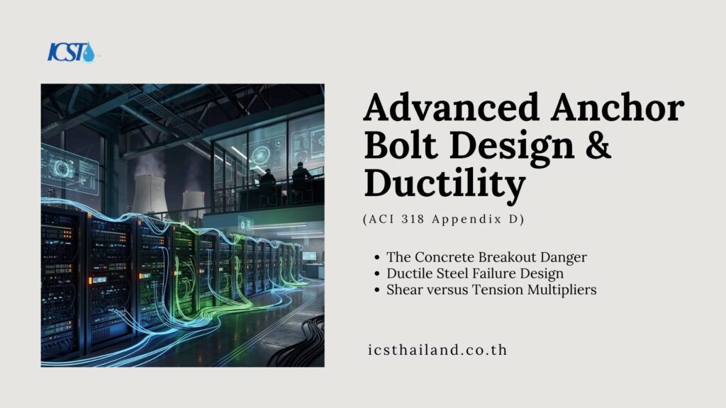
The Concrete Breakout Danger
During seismic events, the concrete surrounding the anchor bolts cracks under pressure. This cracking reduces traditional gripping strength. Engineers must select anchors certified to hold firm inside these tension cracks.
Ductile Steel Failure Design
Civil engineers must design anchor bolts for ductile yielding. The steel bolt must stretch elastically under extreme tension before the concrete fractures. This controlled stretching absorbs violent energy and helps prevent collapse.
Shear versus Tension Multipliers
We apply a dynamic load multiplier to our anchor calculation models. This multiplier factors in simultaneous vertical shaking and horizontal thrust. Even experienced engineers sometimes overlook critical details regarding dynamic load multipliers. An independent peer review helps confirm these calculations.
Frame Stability: Cross Bracing and Structural Detailing
High-stiffness cross bracing is essential to distribute lateral loads evenly. We use heavy structural steel or Fiber-Reinforced Polymer (FRP) frames to control drift limits.
Pre-Stressed Structural Joints
Rigid joints often fail when forced to move. We design structural connections that permit minor, controlled geometric movement. This connection reinforcement prevents snapping rivets or tearing bolt holes during violent shaking.
Low Center-of-Gravity Configuration
Moving heavy equipment into rigid structural cradles improves structural behavior. We place gearboxes and fan assemblies low to resist rotation and top-heavy sway. Dynamic analysis and finite element analysis verify these placements against specific earthquake records.
Decoupling the Systems: Flexible Piping Connections
Your cooling tower connects to the main facility through large piping systems. Rigid piping connections act as destructive levers during ground motion.
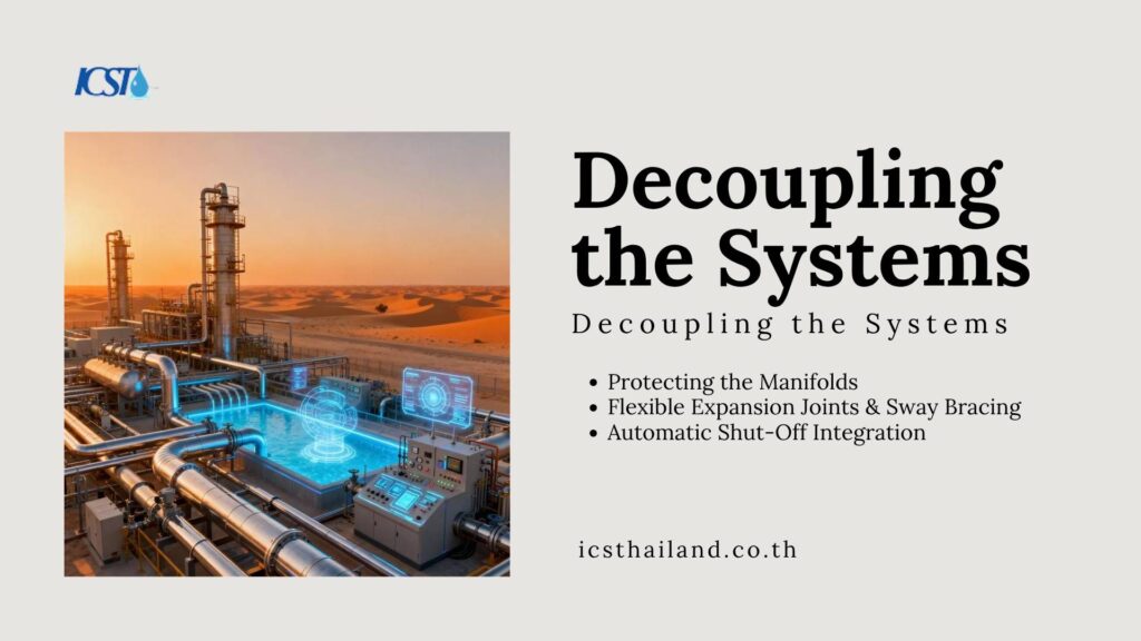
Protecting the Manifolds
Differential movement between the building and the tower causes severe damage. As the tower sways, rigid pipes tear cleanly through fiberglass basins. We must decouple the towers from the main structure.
Flexible Expansion Joints & Sway Bracing
We implement multi-axis braided stainless steel loops on the condenser supply lines. This piping flexibility absorbs the independent building-to-tower movement. Effective seismic bracing on the pipelines ensures operational safety.
Automatic Shut-Off Integration
We size seismic tripping valves to isolate the basin water loop automatically. If a pipe ruptures, these valves prevent massive flooding. This automated response is a cost-effective alternative to extensive water damage repair.
Secure Your Industrial Assets
Relying on generic engineering standards leaves your facility vulnerable to catastrophic failure. A cooling tower lacking proper design and seismic bracing risks complete collapse.
At International Cooling Solutions (Thailand), our independent engineers deliver robust design models that meet all international standards. We tailor your cooling tower seismic design requirements directly to your specific site class and regional parameters. Contact our engineering division today to protect your critical investments.
Frequently Asked Questions
What are the cooling tower seismic design requirements?
Cooling tower seismic design requirements ensure structural resilience during seismic events. These include proper anchor bolt systems, cross bracing, and compliance with ASCE 7 and IBC codes. The goal is to distribute lateral loads effectively, prevent structural failure, and maintain operational safety. Proper design protects critical infrastructure and ensures compliance with international engineering standards.
How do seismic loads affect cooling towers?
Seismic loads create lateral forces that impact cooling tower stability. Dynamic fluid sloshing and ground motion amplify these forces, stressing structural frames and anchor systems. Proper seismic bracing, flexible connections, and robust design mitigate these effects, ensuring the tower withstands earthquake forces without compromising structural integrity or operational continuity.
Why is flexible piping important in seismic design?
Flexible piping absorbs differential movement between cooling towers and connected structures during seismic activity. Rigid pipes can act as destructive levers, causing fractures and damage. Multi-axis flexible connections and seismic tripping valves protect manifolds and ensure operational safety, preventing catastrophic failures in critical infrastructure.
What is the role of cross-bracing in cooling tower design?
Cross bracing enhances frame stability by distributing lateral seismic forces evenly. High-stiffness configurations like diagonal or X-braces prevent structural racking and collapse. Pre-stressed joints and low center-of-gravity designs further improve resilience, ensuring the tower remains stable during seismic events.
How does ASCE 7 Chapter 13 impact cooling tower design?
ASCE 7 Chapter 13 provides guidelines for calculating seismic forces on non-structural components like cooling towers. It defines parameters like importance factors, amplification, and response coefficients to ensure robust anchorage and structural safety. Compliance with these standards minimizes risks and ensures the tower withstands seismic forces effectively.