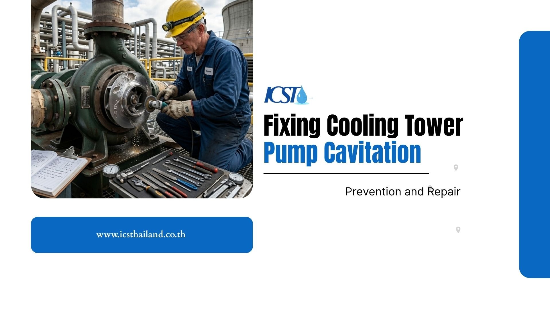
Cooling tower pump cavitation occurs when pressure inside the pump drops below the liquid vapor pressure, causing destructive vapor bubbles to form and collapse violently against internal metal surfaces. This process rapidly damages pump components through impeller erosion, vibration, noise, and seal failure.
Most cavitation problems originate from poor suction pressure, insufficient NPSH, improper piping design, elevated water temperature, or unstable operating conditions. Effective cavitation prevention requires correct hydraulic design, stable basin levels, proper pump selection, and continuous monitoring of pressure, vibration, and flow conditions throughout the cooling system.
What Actually Happens During Pump Cavitation
How Vapor Bubble Formation Starts Inside the Pump
As water enters the pump suction nozzle, the fluid pressure drops significantly, often falling below the liquid’s vapor pressure right at the impeller eye. This pressure drop is a primary trigger for cooling tower pump cavitation, forcing the liquid to boil even at ambient temperatures.
Boiling creates a multitude of tiny vapor bubbles within the fluid stream. Cooling tower systems face extreme vulnerability during high-temperature summer operations. Warmer water requires a smaller pressure drop to reach its boiling point.
Why Bubble Collapse Causes Mechanical Damage
These vapor bubbles move rapidly through the impeller passages until they reach higher-pressure zones. The implosion creates extremely high localized shockwaves directly against the metal surface.
Over time, this repeated collapse causes:
- Severe impeller erosion
- Metal pitting
- Bearing stress
- Shaft vibration
- Seal failure
- Loss of hydraulic efficiency
Operators often describe the sound as gravel or marbles moving through the pump casing.
Imploding bubbles generate microscopic shockwaves that strike the nearby metal surfaces. Repeated shockwaves act like tiny hammers striking the impeller blades continuously. This relentless attack creates deep pitting and accelerates impeller erosion.
Common Symptoms Operators Notice First
Operators can often detect the onset of cooling tower pump cavitation by listening for abnormal sounds and looking for physical changes in the equipment. You must investigate immediately when you notice any of these operational irregularities.
Pay close attention to these early warning indicators:
- Loud Crackling Noises: Hear a sound similar to gravel or marbles being pumped? This is a classic sign of cavitation.
- Excessive Vibration: Notice the pump, piping, or baseplate shaking more than usual? This vibration indicates internal instability.
- Unstable Flow: Is the fluid discharge fluctuating or sputtering? Inconsistent flow is a direct result of vapor bubbles collapsing.
- Erratic Motor Load: See the motor’s power readings jumping erratically on the control panel? This shows the pump is struggling to maintain a steady operation.
Root Causes of Cooling Tower Pump Cavitation
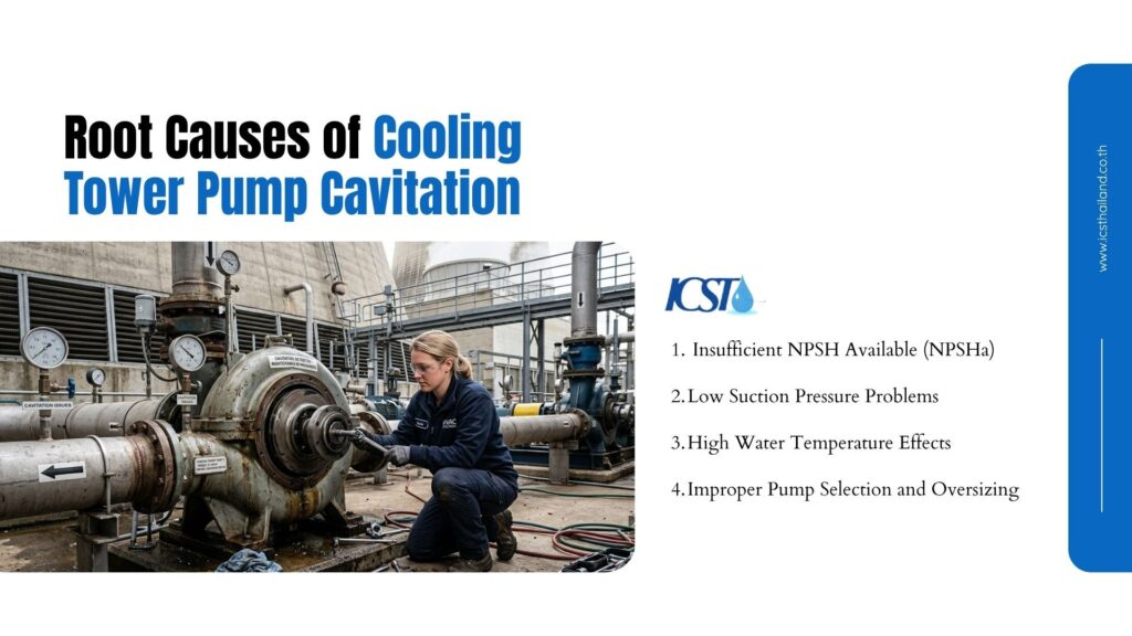
Insufficient NPSH Available (NPSHa)
The most common cause of cooling tower pump cavitation is insufficient Net Positive Suction Head Available (NPSHa).
NPSH represents the pressure margin required to keep water in liquid form at the pump inlet. When available pressure falls below the pump’s required pressure threshold, vaporization begins immediately.
Pump manufacturers specify the minimum required pressure as NPSHr.
Safe operation requires:
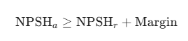
If this margin disappears, cavitation develops rapidly.
Several factors reduce NPSHa:
- Low basin water level
- Excessive suction lift
- Long suction piping
- High water temperature
- Excessive flow velocity
Many facilities ignore NPSH calculations during retrofits or capacity upgrades, which creates chronic cavitation conditions later.
Low Suction Pressure Problems
Suction pressure instability is another major contributor. Cooling tower systems frequently develop suction restrictions over time.
Common causes include:
- Clogged suction strainers
- Partially closed isolation valves
- Undersized piping
- Collapsed flexible connectors
- Air entrainment
- Internal pipe scaling
Even minor restrictions can create major pressure loss because centrifugal pumps are highly sensitive to suction conditions.
Air leakage on the suction side worsens the problem significantly by introducing unstable flow conditions near the impeller eye.
High Water Temperature Effects
Temperature directly affects vapor pressure. As water temperature increases, the pressure required for vaporization decreases. This means warm cooling tower water cavitates much more easily than colder water.
During high thermal loading conditions:
- Basin temperatures rise
- Vapor pressure increases
- NPSH margin decreases
- Bubble formation accelerates
Facilities operating near pump design limits often experience seasonal cavitation during peak summer demand. The hydraulic margin simply disappears under hotter operating conditions.
Improper Pump Selection and Oversizing
Incorrect pump sizing creates major operational instability. Oversized pumps frequently operate far from their Best Efficiency Point (BEP).
Off-BEP operation causes:
- Internal recirculation
- Turbulence
- Uneven hydraulic loading
- Low-pressure zones
These unstable conditions dramatically increase cavitation risk.
Similarly, excessive pump speed increases suction velocity and lowers local pressure at the impeller eye, leading to issues like cooling tower pump cavitation.
Engineering Diagnosis Process for Cavitation Problems
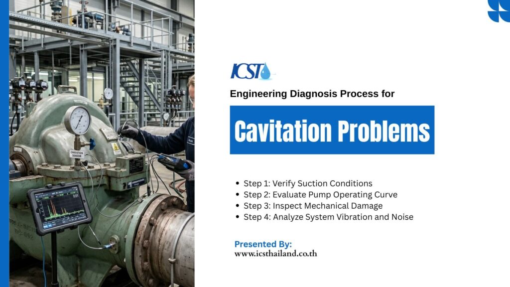
Step 1: Verify Suction Conditions
Begin your investigation by examining the physical fluid supply pathway. You need accurate data to understand the current hydraulic environment.
Execute these diagnostic steps immediately:
- Measure the actual pressure directly at the pump suction nozzle.
- Inspect all basket strainers and suction piping for debris blockages.
- Check the cooling tower water basin to confirm proper fluid levels.
- Look for vortexing or air entrainment sources near the suction intake.
Step 2: Evaluate Pump Operating Curve
Compare your actual operating data against the manufacturer’s published performance curve. Verify that your system flow and head requirements match the original design. Review the motor speed and confirm the installed impeller diameter. Deviations from the original specifications often explain poor performance.
Step 3: Inspect Mechanical Damage
Shut down the equipment and open the pump casing for visual inspection. The specific damage patterns reveal the exact nature of your hydraulic problem.
Look closely for these specific damage signatures:
- Examine the impeller vanes for sponge-like pitting and material loss.
- Inspect the mechanical seals and bearings for heat discoloration.
- Check the main drive shaft for deflection or misalignment.
- Evaluate the overall severity of the metal degradation.
Step 4: Analyze System Vibration and Noise
Vibration analysis tools provide empirical data about internal mechanical health. These instruments separate normal operational frequencies from destructive forces.
Monitor the equipment for abnormal high-frequency sound signatures. Acoustic testing helps distinguish cavitation issues from standard bearing failures. You can use this data to justify system modifications to management.
Relationship Between NPSH and Cavitation Prevention
Understanding NPSH Available vs Required
Pump manufacturers test their equipment to determine the exact NPSH Required (NPSHr). System designers calculate the NPSH Available (NPSHa) based on site conditions.
You must maintain a healthy safety margin between these two values. Experts recommend keeping available energy at least three feet higher than required energy. A robust margin absorbs temporary system fluctuations without causing equipment damage.
NPSH Formula for Cooling Tower Pumps
Engineers use a standard mathematical equation to evaluate suction conditions accurately. You must calculate every variable to ensure system stability.
Use this specific formula for your evaluations:
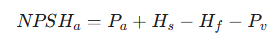
Where:
- P_a equals the atmospheric pressure head at your facility elevation.
- H_s equals the static suction head (water level above the pump).
- H_f represents the total friction losses in your suction piping.
- P_v equals the vapor pressure head of the water at operating temperature.
How Engineers Increase NPSHa
You can manipulate system variables to increase your available suction energy. Small adjustments often yield significant improvements in pump reliability.
Implement these engineering solutions to boost available energy:
- Increase the cooling tower basin water level to add static head.
- Remove unnecessary elbows to reduce suction piping friction losses.
- Lower the cooling water temperature to decrease the fluid vapor pressure.
- Install larger diameter suction piping to slow the fluid velocity.
Cavitation Prevention Strategies for Cooling Towers
Proper Suction Piping Design
Excellent pump performance and preventing cooling tower pump cavitation begin with flawless suction piping design. You must provide a smooth, undisturbed flow of water to the impeller eye.
Follow these piping configuration rules strictly:
- Install a straight pipe for at least five to ten pipe diameters before the inlet.
- Eliminate sharp elbows or restrictive fittings near the suction nozzle.
- Size the suction pipe one or two sizes larger than the pump inlet.
- Route piping carefully to prevent high points where air pockets accumulate.
Maintaining Stable Basin Water Levels
Low basin levels reduce the static suction head immediately. Reliable makeup water control is critical.
Facilities should monitor:
- Float valve performance
- Basin evaporation rate
- Makeup valve operation
- Overflow conditions
An unstable basin level is one of the easiest cavitation causes to correct
Operating Pumps Near Best Efficiency Point
Centrifugal pumps require operation within their designated efficiency zones. You maximize equipment lifespan when you respect the manufacturer’s performance curve.
Avoid throttling the pump discharge valve excessively to control flow. Throttling shifts the operating point away from the BEP and increases vibration. Install Variable Frequency Drives (VFDs) to control flow rates safely and efficiently.
Water Temperature Management
Thermal control directly impacts fluid vapor pressure and system stability. You must reject heat efficiently to protect your pumping equipment.
Reduce the thermal loading on the cooling tower whenever possible. Improve tower airflow to maximize the evaporative cooling effect. Maintain stable water temperatures to prevent sudden spikes in vapor pressure.
Repair Methods After Cavitation Damage
Impeller Repair vs Replacement
Engineers must evaluate damaged components to determine the most cost-effective solution after experiencing cooling tower pump cavitation. You have several options depending on the severity of the wear.
Minor pitting allows technicians to rebuild the vanes using advanced epoxy compounds. Severe impeller erosion compromises structural integrity and demands total component replacement. Consider upgrading to stainless steel materials to resist future pitting damage.
Seal and Bearing Replacement
Cavitation creates continuous vibration that destroys bearings and seals. Repairs commonly include:
- Bearing replacement
- Mechanical seal replacement
- Shaft inspection
- Coupling realignment
Complete vibration analysis should follow every repair.
System Corrections Before Restart
Repairing the pump without fixing the root cause guarantees a repeat failure. You must correct the hydraulic deficiencies before applying power to the motor.
Verify that you have restored proper suction pressure at the inlet. Recalculate your energy margin to confirm the system is now safe. Conduct a comprehensive startup inspection to verify smooth, quiet operation.
Cavitation Risk Comparison Table
| Operating Condition | Cavitation Risk | Common Cause | System Impact | Engineering Recommendation |
| Low suction pressure | Very High | Restricted inlet | Severe impeller erosion | Increase suction head |
| High water temperature | High | Elevated vapor pressure | Flow instability | Improve cooling |
| Oversized pump | Moderate | Off-BEP operation | Internal recirculation | Resize pump |
| Clogged strainers | High | Suction restriction | Pressure drop | Regular cleaning |
| Proper NPSH margin | Low | Stable suction conditions | Reliable performance | Maintain monitoring |
Warning Signs That Require Immediate Shutdown
Severe Noise and Vibration
When you hear severe noise and vibration from your cooling tower pump, it’s a critical warning sign of advanced cavitation. Loud grinding sounds and rapid vibration increases suggest the impeller is being damaged by massive fluid vaporization.
This cooling tower pump cavitation can lead to mechanical destruction very quickly. Shut the motor down immediately to prevent a catastrophic housing fracture.
Sudden Flow Reduction
Fluid transport is the primary function of your centrifugal pump. A sudden drop in output signals a severe hydraulic collapse.
Loss of cooling capacity threatens your entire production process. Pressure instability indicates the pump can no longer maintain a solid fluid column. Stop the equipment to protect the system from complete thermal overload.
Visible Mechanical Damage
Fluid spraying from the mechanical seal indicates total containment failure. Extreme bearing housing temperatures suggest impending bearing seizure. Stop the unit immediately if you find metallic debris in the downstream strainers.
Conclusion
Cooling tower pump cavitation is one of the most destructive hydraulic failures affecting industrial cooling systems. Left unresolved, collapsing vapor bubbles rapidly destroy impellers, bearings, seals, and internal pump surfaces through severe impeller erosion and vibration damage.
Successful cavitation prevention depends on maintaining proper NPSH, stable suction pressure, correct piping design, and controlled operating temperatures. Facilities that combine hydraulic optimization with preventive monitoring dramatically improve pump reliability, reduce maintenance costs, and extend equipment lifespan.
For effective, value-added solutions, visit the ICST website for more cooling tower-related services and maintenance.
Frequently Asked Questions
What causes cooling tower pump cavitation?
Pump starvation occurs due to low inlet pressure and insufficient fluid energy. High water temperatures increase the fluid vapor pressure dangerously. Physical flow restrictions like clogged strainers create sudden pressure drops at the inlet.
How do you identify cavitation in a pump?
Operators hear a distinct crackling noise resembling rocks passing through the casing. The equipment exhibits severe physical vibration and erratic motor current readings. Technicians ultimately find severe metal pitting during internal visual inspections.
What is the role of NPSH in cavitation prevention?
Net Positive Suction Head represents the absolute pressure margin keeping the fluid liquid. You must maintain available energy at a level higher than the required energy. This energy surplus prevents the water from boiling inside the pump casing.
Can cavitation destroy a cooling tower pump?
Yes, this phenomenon aggressively destroys thick metal components over time. The shockwaves erode impellers, shatter mechanical seals, and ruin precision bearings. The resulting imbalance drastically reduces the overall lifespan of the pumping equipment.
How do engineers prevent pump cavitation?
Engineers design proper suction piping with minimal friction and adequate diameter. Operators maintain stable cooling tower basin levels to preserve static head. Facilities manage thermal loads carefully and ensure pumps run near their peak efficiency point.