Optimizing data center cooling tower PUE involves reducing energy consumption while maintaining high reliability. Key strategies include implementing N+2 redundancy to ensure efficient load distribution and leveraging free cooling hours to minimize chiller dependency.
Tight approach temperatures, between 1.5°C and 2.5°C, enhance thermal efficiency, while advanced hydronic balancing eliminates pressure imbalances. Incorporating water-side economizers and improving Water Usage Effectiveness (WUE) further supports sustainable operations. These measures not only lower operational costs but also ensure five-nines reliability, making them essential for modern data center cooling tower efficiency.
The Metrics of Critical Infrastructure: Total PUE vs. Mechanical PUE (mPUE)
Understanding power usage effectiveness requires dividing the metric into actionable categories. Total facility PUE targets must drop below 1.15 to handle modern artificial intelligence workloads efficiently.
Isolating Mechanical PUE (mPUE)
Mechanical PUE (mPUE) defines the specific sub-metric that matters most to thermal engineers. You calculate mPUE by adding the IT load power to the cooling infrastructure power (fans, pumps, and chillers), and dividing that sum by the IT load power. This calculation isolates the exact energy footprint of your thermal management systems.
The PUE vs. WUE Sustainability Paradox
Open evaporative tower loops lower PUE by leveraging latent heat dissipation. However, this process introduces massive data center water footprints through continuous evaporation and blowdown. Balancing this reality with strict Water Usage Effectiveness (WUE) metrics remains critical for modern resource management. You must optimize both power efficiency and water utilization concurrently.
Engineering Sizing and Operational Matrix
Achieving an optimal data center balance requires aligning mechanical redundancy configurations directly with thermodynamic load profiles. The table below summarizes key engineering vectors and their impact on PUE optimization and reliability:
| Engineering Vector | Infrastructure Specification | PUE Optimization Impact | Redundancy & Reliability Metric |
| Redundancy Layout | N+2 Cellular Design connected to a common hydronic header. | Lowers individual cell load; allows all fans to run at peak efficiency points. | Concurrently Maintainable (Tier III / Five-Nines) |
| Economizer Interface | Water-Side Plate & Frame Economizer with automatic chiller bypass. | Drops compressor power draw to zero during favorable wet-bulb seasons. | Maximizes annual free cooling hours |
| Hydronic Balancing | Automated variable-flow pumps with multi-axis flexible piping loops. | Eliminates dynamic pressure imbalances and prevents system friction losses. | Eliminates structural acoustic bridging risks |
| Water Efficiency | Side-stream Reverse Osmosis (RO) blowdown recovery loops. | Minimizes wastewater volume while maximizing Cycles of Concentration (CoC). | Lowers target Water Usage Effectiveness (WUE) |
- Redundancy Layout: Utilize an N+2 cellular design connected to a common hydronic header. This lowers individual cell load and allows all fans to run at peak efficiency points. It concurrently secures and maintains five-nines reliability.
- Economizer Interface: Deploy a water-side plate and frame economizer with automatic chiller bypass. This drops compressor power draw to zero during favorable wet-bulb seasons. It maximizes annual free cooling hours.
- Hydronic Balancing: Install automated variable-flow pumps with multi-axis flexible piping loops. This eliminates dynamic pressure imbalances and prevents system friction losses.
- Water Efficiency: Implement side-stream reverse osmosis (RO) blowdown recovery loops. This minimizes wastewater volume while maximizing cycles of concentration. It significantly lowers your target Water Usage Effectiveness (WUE).
Maximizing Free Cooling Hours: The Approach Temperature Equation
The approach temperature defines the difference between the cold water leaving the cooling tower and the ambient outdoor wet-bulb temperature. Engineering a tight approach profile between 1.5 degrees Celsius and 2.5 degrees Celsius is the single most critical factor for data center PUE optimization.
Extending Water-Side Economizer Windows
Maximizing internal tower fill surface areas allows the data center to run entirely on free cooling during extended seasonal windows. This strategy turns off energy-intensive chiller compressors completely. A lower approach temperature expands the ambient temperature window where mechanical cooling remains unnecessary.
Managing Extreme Return Temperatures
Next-generation server racks utilize direct-to-chip liquid cooling loops. These systems return water to the loop at significantly higher temperatures, typically between 38 degrees Celsius and 45 degrees Celsius. This elevated temperature expands the thermal driving force. The cooling tower can reject heat much more efficiently under these conditions.
Redundancy Design Architecture: N+1, N+2, and 2N Configurations
Data center engineers must choose the correct redundancy model to protect critical operations. Traditional fully mirrored 2N cooling systems suffer from low efficiency. Keeping an entire duplicate cooling plant running at ultra-low part-loads creates parasitic energy drains that degrade mPUE.
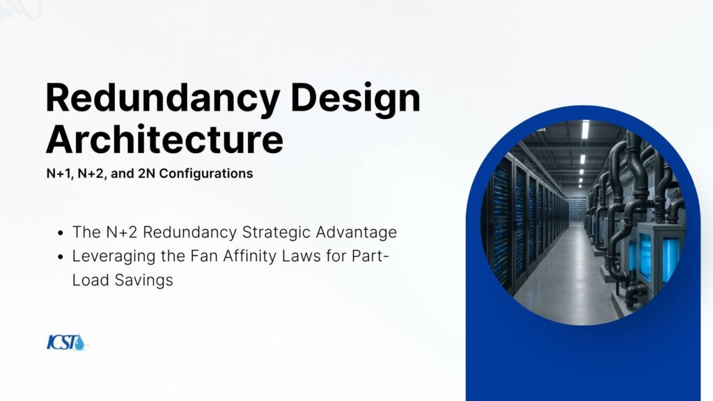
The N+2 Redundancy Strategic Advantage
The N+2 redundancy configuration offers a superior alternative. This setup utilizes a unified modular multi-cell tower array where “N” matches the required load capacity. Two extra modules join the active loop. This enables simultaneous maintenance and provides robust failure protection without requiring an entire secondary plant.
Leveraging the Fan Affinity Laws for Part-Load Savings
Fluid mechanics dictate that fan brake horsepower is proportional to the cube of the fan speed. This principle defines the Fan Affinity Laws. By using an N+2 design, all available tower cells run continuously at reduced fan speeds via individual variable frequency drives. This approach satisfies the full heat load while consuming significantly less power than running fewer cells at maximum capacity.
Eliminating the Single Point of Failure: Fluid Dynamics and Physical Isolation
Mechanical failures must never disrupt the IT computing environment. You must engineer physical isolation protocols to protect the wider infrastructure network.
Rooftop Vibration Protection
Deploy heavy inertia bases and vertically restrained spring isolators beneath the cooling tower dunnage. This prevents mechanical fan vibrations from transmitting into the building structure. Proper isolation protects sensitive IT hardware and delicate fiber networks.
Dynamic Header Isolation
Integrate motorized, fast-acting isolation valves on every individual cooling tower module. If a single cell experiences a fan motor failure or a basin leak, the system instantly isolates it. This action prevents pressure drops or interruptions across the remaining active modules.
Automated Sump Equalization
Design oversized gravity-balancing lines between modular basins to manage varying water levels. This mechanism prevents sump starvation or unexpected overflows during sudden load changes. Continuous equalization ensures stable pump operation at all times.
Future-Proof Your Data Center Infrastructure
Managing next-generation enterprise workloads requires high-performance thermal design that protects your uptime metrics while lowering your operational costs. Optimizing data center cooling tower PUE is essential to future-proof your data center infrastructure against accelerating compute densities.
At International Cooling Solutions (Thailand), our dedicated mission-critical engineers design custom, high-efficiency data center cooling tower networks optimized for maximum water-side economization and resilient N+2 configuration safety.
Contact our Bangkok office today to schedule a comprehensive technical thermal and PUE audit.
Consult a Data Center Infrastructure Engineer
Frequently Asked Questions (FAQs)
What is data center cooling tower PUE, and why is it important?
Data center cooling tower PUE (Power Usage Effectiveness) measures the energy efficiency of cooling systems relative to IT load. A lower PUE indicates better efficiency, reducing operational costs and environmental impact. Optimizing PUE ensures reliable cooling for high-density compute clusters while maintaining five-nines uptime, making it critical for modern data centers.
How does N+2 redundancy improve cooling tower efficiency?
N+2 redundancy ensures all cooling tower cells operate at optimal efficiency by distributing the load evenly. This configuration allows for simultaneous maintenance and failure protection without requiring a duplicate system. It reduces energy consumption and enhances reliability, aligning with PUE optimization goals.
What role does approach temperature play in cooling tower performance?
Approach temperature is the difference between the cooling tower’s cold water temperature and the outdoor wet-bulb temperature. A tighter approach (1.5°C–2.5°C) improves thermal efficiency, maximizing free cooling hours and reducing reliance on energy-intensive chillers, which directly impacts PUE.
Why is Water Usage Effectiveness (WUE) critical alongside PUE?
While PUE focuses on energy efficiency, WUE addresses water consumption in evaporative cooling towers. Optimizing WUE minimizes water waste and environmental impact, ensuring sustainable operations. Balancing both metrics is essential for modern data center cooling strategies.
How can free cooling hours reduce operational costs?
Free cooling hours leverage favorable outdoor conditions to bypass mechanical chillers, relying solely on cooling towers. This significantly lowers energy consumption and operational costs while maintaining optimal thermal performance, contributing to a lower PUE and sustainable data center operations.