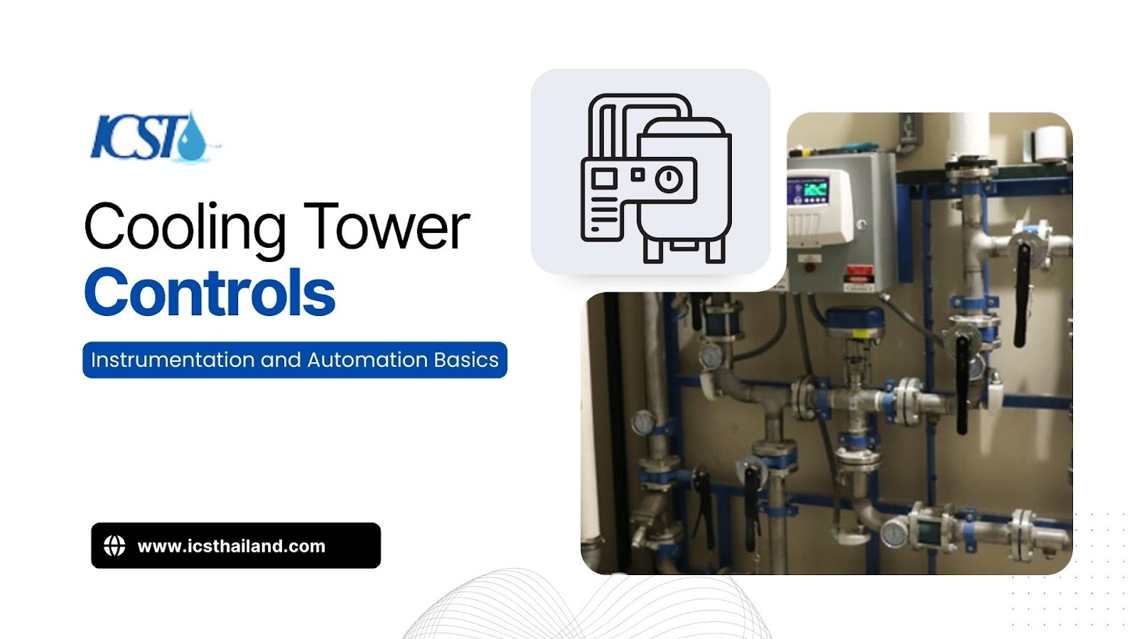
In any industrial setting, keeping things cool isn’t just a luxury; it’s a critical balancing act between efficiency, energy use, and equipment health. How do engineers master this challenge? They turn to advanced cooling tower controls that automatically adjust temperature, manage water flow, and adapt to fluctuating heat demands on the fly.
Without precise control, cooling systems waste energy and risk process instability. Moving from manual oversight to automated cooling strategies improves performance significantly.
In this blog, we will delve into the foundational elements of these systems, from core instrumentation to the PLC control system logic that drives them, providing authoritative insights into their functionality and design.
Cooling Tower Control System Overview
A control system serves as the brain of the cooling infrastructure. Its primary purpose is to maintain process variables, such as water temperature and flow rate, at specific setpoints while minimizing energy usage and ensuring safety.
Understanding the architecture of these systems helps operators troubleshoot issues and optimize performance. A typical control architecture consists of several distinct layers that work in unison:
- Sensors (Inputs): These devices measure physical parameters like temperature, flow, and pressure, converting them into electrical signals.
- Controllers (PLC/DCS): The programmable logic controller receives sensor inputs, processes the logic, and determines necessary adjustments.
- Actuators (Outputs): These mechanical devices, including valves, Variable Frequency Drives (VFDs), and dampers, execute the commands sent by the controller.
- Human Interface (HMI/SCADA): This layer allows operators to monitor system health, adjust setpoints, and view historical data.
Main Instrumentation Components

Reliable automation begins with accurate measurement. The controller can only act upon the data it receives, making the selection and placement of instrumentation critical for successful cooling tower controls.
Temperature Sensors
Temperature is the primary variable in cooling applications. Control systems typically utilize resistance temperature detectors (RTDs) or thermocouples to provide accurate, real-time feedback on heat exchange performance.
Engineers must place these sensors strategically to gather the most relevant data. Common placement locations include:
- Inlet Temperature: Measures the hot water returning from the process to the tower.
- Outlet Temperature: Measures the cooled water leaving the basin, which serves as the primary process variable for fan control.
- Ambient Temperature: Measures the wet-bulb temperature of the surrounding air to determine the theoretical cooling limit.
Flow Sensors / Flow Meters
Flow meters ensure the system circulates the correct volume of water. Without adequate flow verification, pumps may run dry, or heat exchangers may foul due to low velocity.
Different technologies offer varying levels of accuracy and maintenance requirements. Frequently used flow measurement devices include:
- Electromagnetic Flow Meters: These offer high accuracy and no moving parts, making them ideal for conductive water.
- Ultrasonic Meters: These clamp-on devices measure flow from the outside of the pipe, which eliminates the need for cutting into the piping.
- Differential Pressure: This traditional method measures the pressure drop across an orifice plate to calculate flow rate.
Level Sensors
Basin water level management prevents overflow and protects pumps from cavitation. Level sensors provide the feedback necessary to open makeup water valves or trigger alarms.
Operators typically choose between mechanical and electronic solutions based on budget and precision needs. Common level sensing technologies include:
- Float Switches: Simple, mechanical devices that trigger a contact closure at a specific height.
- Ultrasonic Level Transmitters: Non-contact sensors that provide continuous level measurement rather than simple on/off points.
Pressure Sensors
Pressure monitoring safeguards the physical integrity of the piping and pumping equipment. Sudden pressure drops often indicate leaks, while spikes can signal blockages or valve failures.
Specific monitoring points provide critical health data for the system. Key pressure applications include:
- Suction/Discharge Monitoring: Ensures pumps operate within their efficiency curve.
- Differential Pressure Monitoring: Measures pressure drop across filters and heat exchangers to detect fouling or blockages.
- System Pressurization: Maintains positive pressure in closed-loop systems to prevent air ingress and cavitation.
- Leak Detection: Identifies pressure losses in the distribution piping.
Control Objectives & Key Parameters
Hardware is only useful when applied to specific control objectives. A robust strategy defines how the system reacts to changes, utilizing distinct logic for temperature control, flow, and level management.
Temperature Control
The primary goal of a cooling tower is to reject heat and maintain a specific basin water temperature. Temperature control logic dictates how fans and bypass valves operate to achieve this setpoint.
Most systems utilize Proportional-Integral-Derivative (PID) loops to maintain stability. The PID controller calculates the error between the setpoint and the actual temperature, adjusting the fan speed via a VFD to close the gap. Operators often apply a deadband to prevent the fans from cycling on and off too frequently, which reduces wear on the motor.
Flow Control
Proper flow rates ensure efficient heat transfer across the fill media. Flow control strategies prevent the system from pumping more water than necessary, which conserves energy.
Automation allows for dynamic adjustments based on system demand. Strategies often include:
- Pump Speed Control: Using VFDs to ramp pump speeds up or down to match the required flow rate.
- Load Balancing: Ensuring equal flow distribution across multiple cells to maximize cooling surface area.
Level Control
Maintaining the correct water level in the cold water basin is essential for continuous operation. The system must account for water lost through evaporation, drift, and blowdown.
The control logic must balance the makeup water input with the blowdown rate. When conductivity sensors trigger a blowdown cycle to reduce mineral concentration, the level control system must simultaneously open the makeup valve to replenish the basin.
Fan Speed & Airflow Control
Fans consume a significant portion of the cooling tower’s energy. Optimizing airflow based on the current heat load and ambient conditions offers the highest potential for energy savings.
Modern systems rarely run fans at 100% speed continuously. Instead, the logic follows a specific path:
- Setpoint: The operator defines the desired outlet temperature.
- Sensor: The outlet RTD measures the actual water temperature.
- Controller: The PLC calculates the difference.
- Actuator: The VFD adjusts the fan motor frequency to increase or decrease airflow.
PLC Control System: The Heart of Automation
The Programmable Logic Controller (PLC) acts as the central processor for industrial automation. A robust PLC control system processes thousands of calculations per second to execute the control strategy reliably.
Industrial PLCs offer modularity and robustness that standard computers cannot match. A typical architecture includes:
- I/O Modules: Digital modules handle on/off signals (switches, alarms), while analog modules handle continuous data (temperature, pressure).
- Ladder Logic: This programming language visualizes electrical circuits. It manages temperature control loops, creates flow interlocks (preventing heater operation without flow), and executes safety shutdowns.
- Redundancy: Critical facilities often utilize backup processors to ensure the cooling tower controls continue functioning even if the primary processor fails.
SCADA Cooling System Integration
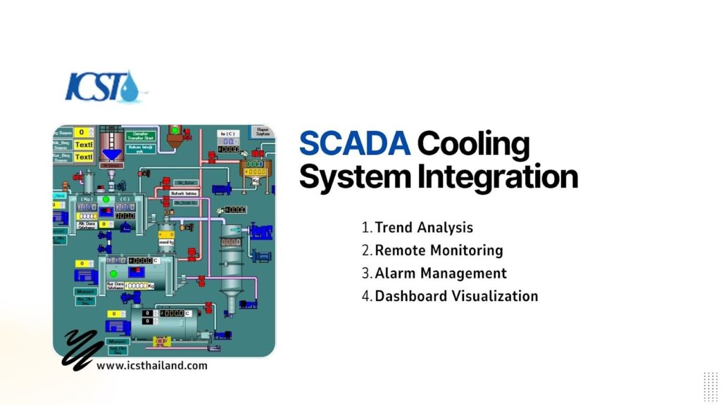
While the PLC handles the immediate logic, Supervisory Control and Data Acquisition (SCADA) systems provide the visual interface and data management. A SCADA cooling system allows operators to view the entire process from a central control room.
This integration transforms raw data into actionable insights. SCADA systems visualize system performance through:
- Trend Analysis: Operators can view temperature and flow trends over weeks or months to identify efficiency degradation.
- Remote Monitoring: Personnel can receive alerts and adjust setpoints from mobile devices or off-site locations.
- Alarm Management: The system logs every fault, creating a historical record that aids in root cause analysis.
- Dashboard Components: Screens typically display control loop status, real-time trend charts, and event logs.
Automated Cooling Strategies
Basic control loops maintain setpoints, but advanced strategies optimize the system for energy efficiency and longevity. Implementing intelligent automated cooling logic separates modern facilities from legacy operations.
Load-Based Automated Control
Cooling demands rarely remain static throughout the day. Load-based control logic automatically brings cooling cells online or offline based on the total heat rejection required.
Instead of running three fans at 30% speed, the system might determine that running one fan at 90% is more efficient. This dynamic adjustment reduces wear on mechanical components and optimizes energy consumption.
Weather-Adaptive Control
The efficiency of a cooling tower depends heavily on the ambient wet-bulb temperature. Weather-adaptive control strategies adjust fan and pump speeds relative to the changing atmospheric conditions.
If the ambient air is cold enough, the system may switch to “free cooling” mode. In this state, the fans may turn off completely, allowing natural draft or bypass flow to provide sufficient cooling without mechanical assistance.
Energy Optimization Strategies
Reducing energy waste lowers operational costs and carbon footprint. Optimization logic looks for opportunities to minimize equipment runtime.
Strategies often involve demand response integration. The system can receive signals from the power grid to reduce load during peak pricing hours, allowing the basin temperature to drift slightly higher within safe limits to save costs.
Safety Interlocks & Alerts
Automation protects valuable capital equipment from catastrophic failure. Safety interlocks override standard control logic to prevent damage.
Common safety protocols programmed into the PLC include:
- High/Low Temperature Cutoffs: Shuts down the process if water becomes too hot or prevents freezing in winter.
- Vibration Switches: Trips the fan motor if excessive vibration is detected, indicating a potential blade failure or gear reducer issue.
- Sensor Failure Alarms: Alerts the operator if a sensor reading drifts out of a realistic range (e.g., reading -50°F in summer).
Common Challenges & Troubleshooting Tips
Even the most advanced cooling tower controls encounter issues. Operators and technicians must recognize common symptoms to maintain system integrity.
Diagnosing these problems requires a systematic approach. Common issues include:
- Symptom: Temperature fluctuates wildly (oscillates) around the setpoint.
- Probable Cause: The PID loop tuning is too aggressive.
-
- Solution: Adjust the proportional band or integral time to dampen the response.
- Symptom: Sensor readings drift slowly over time.
- Probable Cause: Scale buildup on the probe or electrical noise.
- Solution: Clean the sensor head or check shielding on the signal cables.
- Symptom: The fan motor trips on overload shortly after starting.
- Probable Cause: The VFD acceleration ramp is set too short, or there’s a mechanical binding in the fan system.
- Solution: Increase the VFD’s acceleration time to reduce inrush current. If the issue persists, inspect the fan blades and gearbox for mechanical issues.
- Symptom: Basin water level is consistently low, triggering makeup water frequently.
- Probable Cause: The level sensor is miscalibrated or has failed, or there is a leak in the basin.
- Solution: Check the level sensor’s calibration against a manual measurement. Inspect the basin for cracks or leaks, especially around piping penetrations.
- Symptom: SCADA shows “Comm Loss.”
- Probable Cause: Network interruption or PLC power failure.
- Solution: Check Ethernet switches and ensure the PLC has power.
Conclusion
The transition from manual oversight to intelligent automation transforms how facilities manage heat rejection. By integrating precise instrumentation with a robust PLC control system, operators gain the ability to maintain tight process windows while reducing energy waste.
A well-designed architecture that includes a SCADA cooling system empowers teams to visualize performance and predict failures before they occur. Ultimately, investing in modern cooling tower controls delivers a clear return on investment through improved reliability, safety, and operational efficiency.
We recommend that facility managers audit their current systems to identify opportunities where temperature-control upgrades and automated cooling strategies can deliver immediate value. Optimize your cooling system with Industrial Cooling Solution Thailand, learn more today!
Frequently Asked Questions
What are cooling tower controls?
Cooling tower controls are automated systems comprising sensors, controllers (PLCs), and actuators that regulate water temperature, flow, and level to ensure efficient heat rejection.
How do PLC systems improve cooling performance?
A PLC control system improves performance by executing complex logic faster and more reliably than manual operation, ensuring precise temperature regulation and energy optimization.
What is the role of SCADA in cooling tower automation?
A SCADA cooling system provides a visual interface for operators to monitor real-time data, analyze historical trends, manage alarms, and adjust settings remotely.
How is temperature control achieved in cooling towers?
Temperature control is achieved by measuring the outlet water temperature and adjusting the speed of the cooling tower fans (via VFDs) or modulating bypass valves to meet the desired setpoint.
Why automate flow control in cooling systems?
Automating flow control ensures the system circulates the exact amount of water needed for the heat load, preventing pump damage and reducing unnecessary energy consumption.