A cooling tower vibration switch protects rotating equipment by detecting excessive vibration and triggering alarms or automatic shutdown. Proper vibration protection logic and an accurate trip setpoint calibration are essential to avoid both equipment damage and unnecessary downtime.
Implementing a reliable system ensures timely fan shutdown and comprehensive gearbox protection. These devices act as critical safety nets for your industrial cooling systems.
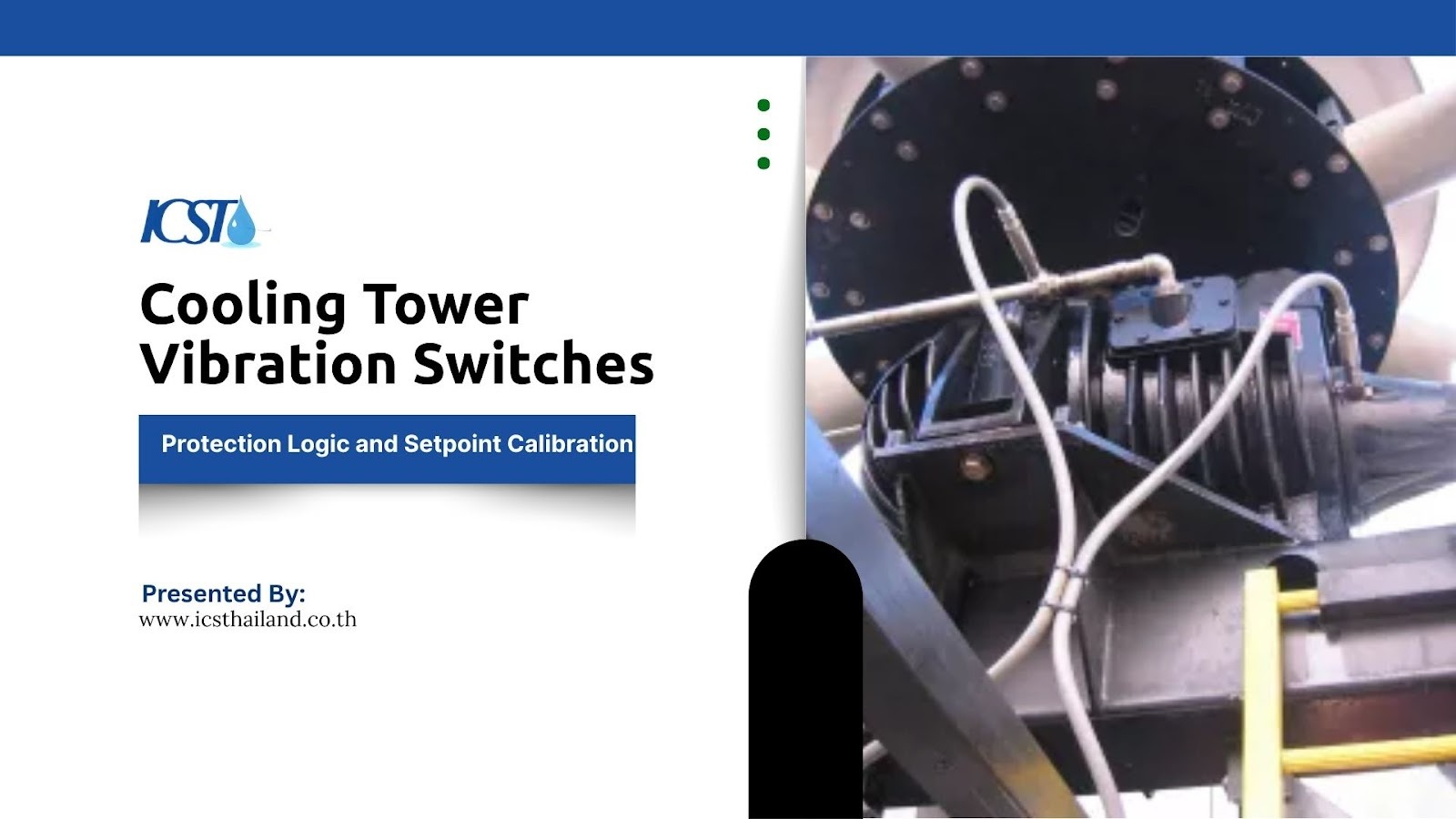
What Is a Cooling Tower Vibration Switch?
Industrial Cooling towers rely heavily on rotating components like fans, motors, and gearboxes. These moving parts remain highly prone to vibration-related failures over time. A cooling tower vibration switch constantly monitors these components to detect abnormal vibration levels.
When vibration exceeds safe limits, the switch triggers an alarm or initiates a shutdown sequence. This rapid response protects critical components from catastrophic failure. How exactly does this device secure your equipment? Consider these key functions:
- It acts as an early warning system before a minor issue becomes a major mechanical failure.
- It detects out-of-balance fan blades or failing bearings instantly.
- It prevents localized damage from spreading to the entire cooling tower structure.
Vibration Protection Logic: How the System Decides to Trip
Protection logic defines how vibration signals translate into real actions like alarms or system shutdowns. Engineers program these devices to understand the difference between normal operational hums and dangerous mechanical faults.
Alarm vs Trip Logic (Two-Level Protection)
Electronic switches often use dual thresholds for staged protection. This two-level approach gives operators a chance to investigate issues before a complete shutdown occurs. How does this dual system operate in practice? Here is how the two levels function:
- The alarm level serves as an early warning that vibration has increased beyond normal baseline parameters.
- The trip level initiates a complete system shutdown to prevent immediate, severe damage.
- Operators use the gap between alarm and trip to schedule maintenance without losing production time.
Time Delay Logic to Prevent False Trips
Cooling towers routinely experience temporary high vibration during initial startup. Without a time delay, the system would shut down every time you turn on the motor. Time delay logic solves this problem effectively. What does this logic actually achieve? Look at these operational benefits:
- It allows the system to ignore transient spikes caused by motor startup torque.
- It prevents unnecessary shutdowns during brief, intense gusts of wind.
- It ensures the switch only reacts to sustained, genuinely dangerous vibration levels.
Fan Shutdown Logic and Safety Interlocks
Fan shutdown logic integrates directly with the motor starter to stop the equipment safely. An emergency shutdown sequence must act swiftly to halt the massive kinetic energy of a cooling tower fan. How do safety interlocks manage this critical process? Consider these integration points:
- The switch sends an immediate signal to the motor control center to cut power.
- Safety interlocks prevent operators from restarting the fan until the fault is cleared.
- The system logs the event in the control room for post-incident analysis.
Understanding Vibration Signals: What Are You Measuring?
Correct calibration depends entirely on understanding the specific vibration parameters of your machinery. Frequency and amplitude indicate the true mechanical condition of the machine.
Engineers measure vibration in several distinct ways to capture a complete picture of equipment health. What metrics do professionals track to ensure safety? Here are the primary measurements:
- Acceleration: Measured in g-force, this metric is crucial for detecting high-frequency issues, such as the initial stages of bearing wear.
- Velocity: Measured in mm/s or in/s, velocity offers the most comprehensive view of a machine’s fatigue and balance, making it a reliable indicator of overall health.
- Frequency: This measurement pinpoints the exact source of a vibration problem, whether it’s a misaligned shaft or another faulty component.
Trip Setpoint Calibration: How to Set the Right Threshold

Incorrect setpoints can either cause unnecessary shutdowns or allow severe damage to occur. Setting the perfect threshold requires precision, patience, and operational data.
Typical Setpoint Ranges for Cooling Towers
Industry standards provide a solid starting point for calibration. Typical setpoints include 1–2g for mechanical switches or approximately 0.6–0.7 in/s for velocity-based electronic systems. What are the standard baselines used by technicians? Review these common ranges:
- Mechanical switches generally trigger a shutdown at a fixed threshold of 1 to 2g.
- Electronic switches use velocity-based limits, often alarming at 0.4 in/s and tripping at 0.7 in/s.
- Customized thresholds apply to highly specialized or variable-speed cooling towers.
Factors Affecting Setpoint Selection
No two cooling towers vibrate the same way. You must account for the unique physical characteristics of your specific installation. What external and internal elements alter your baseline? Consider these crucial factors:
- Fan size and motor speed dictate the natural operating frequency of the tower.
- The physical structure type (wood, fiberglass, or concrete) absorbs vibration differently.
- Environmental conditions like heavy ice buildup or nearby heavy machinery impact baseline readings.
Step-by-Step Calibration Process
Calibration is a methodical process that demands strict attention to detail. You cannot simply guess the correct limits for your cooling tower vibration switch.
How do experts dial in the perfect settings? Follow this standard progression:
- Establish a Baseline: First, measure the tower’s vibration during normal, healthy operation. This provides a reference point for your adjustments.
- Fine-Tune the Threshold: Gradually adjust the sensitivity settings. The goal is to find the sweet spot where the switch is sensitive enough to detect genuine issues without triggering false alarms.
- Validate with a Test: Finally, simulate a fault condition to confirm that the switch activates correctly. This ensures it will protect the system when a real problem occurs.
Common Calibration Mistakes That Lead to System Failure
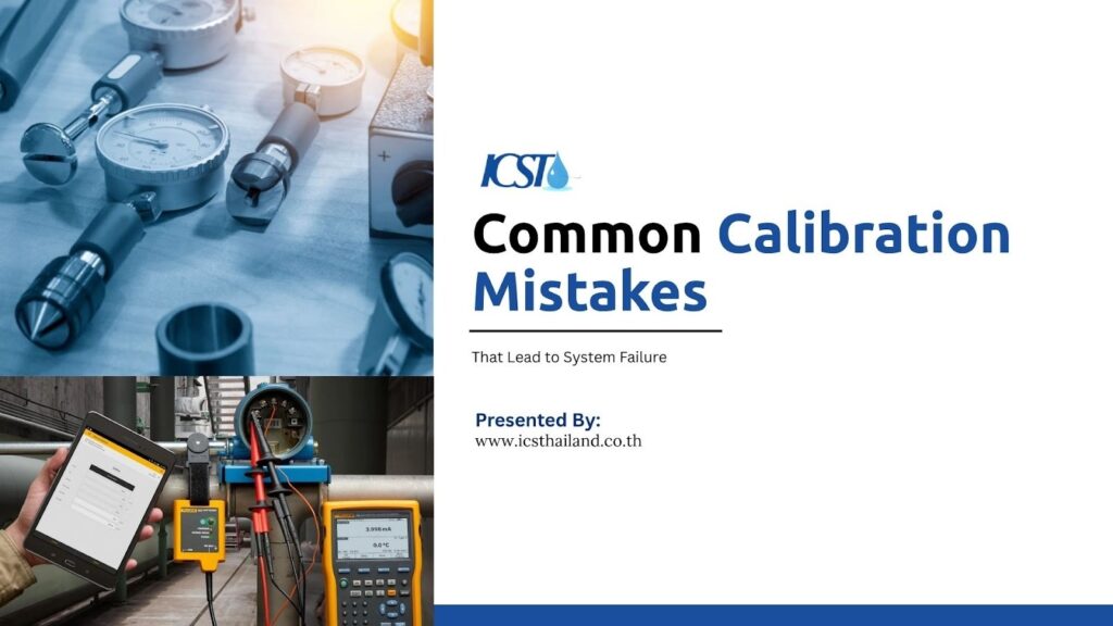
Even experienced technicians occasionally make errors during the setup process. These mistakes compromise the safety and efficiency of the cooling system. What traps should you avoid when configuring your devices? Watch out for these common errors:
- Setting the threshold too low: This causes constant false alarms, frustrating operators and leading to the switch being ignored or disabled.
- Setting the threshold too high: This results in delayed protection, which can allow catastrophic damage to occur before the system shuts down.
- Ignoring startup vibration: Failing to account for the temporary, higher vibration levels during motor startup will cause the system to trip unnecessarily every time it’s turned on.
- Using the wrong sensor for the application: Selecting a sensor not designed for the specific frequency range or environmental conditions of the cooling tower can lead to inaccurate readings and unreliable protection.
- Improper sensor mounting: A loose or incorrectly mounted sensor won’t transmit vibrations accurately, making the entire monitoring system ineffective. Even the right torque and surface preparation are critical.
- Neglecting regular maintenance and recalibration: Vibration switches can drift over time due to environmental stress or electronic aging. Assuming a “set it and forget it” approach is a recipe for silent failure.
Mechanical vs Electronic Vibration Switches: Which One to Choose
When selecting a cooling tower vibration switch, choosing the right type impacts the accuracy and reliability of your protection scheme. Each technology offers distinct advantages depending on your budget and operational needs.
Mechanical Switches
Mechanical switches rely on a spring and magnet mechanism to detect movement. They offer a straightforward approach to equipment protection. Why do some facilities still prefer this older technology? Consider these practical benefits:
- They remain incredibly simple to install and wire into basic control panels.
- They provide a highly cost-effective solution for smaller, less critical cooling towers.
- They operate without requiring an external power supply.
Electronic Switches
Electronic switches utilize internal accelerometers and microprocessors to analyze movement. These modern devices provide more accurate measurement and control. What makes electronic variants the superior choice for critical infrastructure? Review these advanced capabilities:
- They offer high sensitivity to detect minute changes in machine health.
- They feature easily adjustable settings for time delays and dual-level alarms.
- They facilitate better monitoring by outputting continuous data to the control room.
Integrating Vibration Switches with Monitoring Systems
Modern industrial facilities demand connected, intelligent systems. A standalone switch provides basic protection, but an integrated system delivers actionable intelligence.
Connecting your cooling tower vibration switch to a central control network elevates your maintenance strategy. How do facilities achieve this high level of integration? Look at these standard connectivity methods:
- Engineers use PLC/DCS integration to centralize all alarm and trip data on the operator dashboard.
- Sensors transmit continuous 4–20 mA signals to represent real-time vibration velocity.
- Data feeds directly into predictive maintenance software to forecast future equipment failures.
Best Practices for Reliable Vibration Monitoring and Protection
Installing the hardware represents only the first step in protecting your assets. You must maintain the system meticulously to ensure it works when you need it most.
Applying consistent best practices guarantees your vibration protection system remains vigilant. What routines ensure maximum reliability? Implement these standard maintenance protocols:
- Select the correct installation location, mounting the sensor solidly against the bearing housing.
- Perform regular testing of the trip circuit to verify the motor actually stops on command.
- Schedule periodic recalibration to account for sensor drift and structural aging.
Final Thoughts
Implementing a robust cooling tower vibration switch fundamentally changes how you manage facility maintenance. By mastering vibration protection logic and dialing in the perfect trip setpoint, you drastically reduce the risk of unexpected mechanical failures.
Accurate calibration ensures that a necessary fan shutdown happens instantly, while false alarms become a thing of the past.
Ultimately, committing to rigorous gearbox protection and continuous vibration monitoring keeps your industrial cooling systems running safely and efficiently year after year.
Frequently Asked Questions
What does a cooling tower vibration switch do?
A vibration switch detects excessive vibration in cooling tower components and triggers an alarm or shutdown to prevent damage. It acts as a protective device for rotating equipment like fans, motors, and gearboxes.
What is the correct trip setpoint for a vibration switch?
Typical trip setpoints range around 1–2g for mechanical switches or about 0.6–0.7 in/s for electronic switches. However, the exact value depends on equipment size, speed, and operating conditions.
Why does my vibration switch trip during startup?
Cooling towers often experience temporary high vibration during startup. Without proper delay settings, the switch may interpret this as a fault and trigger a shutdown.
What is the difference between alarm and trip setpoints?
An alarm setpoint provides an early warning when vibration increases, while a trip setpoint triggers automatic shutdown to prevent damage.
How can false trips be prevented?
False trips can be avoided by setting appropriate thresholds, adding time delays, and calibrating the switch based on actual operating conditions.